Archive

Posts Tagged ‘transformers’

Transformer Replacement will Often not be an Exact Replacement

July 8th, 2011 Comments off

At MIDWESTwe often get calls or receive inquiries from individuals or company employees seeking an exact transformer replacement for a particular unit.  The reasons are numerous.  Their existing transformer failed suddenly or they have a transformer that is in the process of failing.  Maybe they are trying to expand their facility with limited funds and do not want to pay for the services of an engineering consultant.  They look around and decide to copy what they already have and reason if they just had another one just like it and moved the walls out a bit, their newly purchased used machine ( another blog at another time) which hopefully will mean more income.  Possibly the building has a new owner and they are looking for a spare transformer (a gold star to them for being pro-active).  ‘Finding another one just like it’ is easy if you are shopping for a jar of Jiff ® or Skippy®.  But looking for running shoes just like the kind you purchased last year can be difficult.  Now you can imagine just how difficult it is to locate an identical twin to transformer in a building over thirty years old, assuming the transformer nameplate exists, is still legible and not covered with paint.  If you are fortunate to have the model or type number, a Google search may yield a possible match. Hopefully it is an available unit for sale and not a line item on a specification for a future construction project.


A GOOGLE search with only the transformer brand will help you find a soulmate who is usually looking for product data or a wiring diagram for that brand of transformer. 

Sadly, some transformer companies are no longer in business, their assets were sold to another company, the factory shuttered and you trail runs cold.


Assuming the transformer was not built for an Arc furnace and is a one-of-a kind relic (see future blog) you can usually replace a transformer that was made by company X with a transformer that was manufactured by Company Y.  To do so requires a complete list of specifications with all available information on the transformer whether you think it is relevant or not.  There are a lot of parameters that need to be known: KVA, footprint, height and weight, impedance and most importantly the primary and secondary voltage and also if this is a single phase or three phase transformer.  You also need to know where the transformer will be used (outdoors, indoors).  If it is a fluid filled unit, what type of fluid?  If it is a dry transformer (conventional dry type or encapsulated).  You have to know if this transformer needs to have high side voltage taps and if the primary and secondary are Delta or Wye.  If it is a large power transformer, where are the bushings and how are they arranged. Doing your homework first before you have the transformer shipped to you from another state will help you avoid the embarrassment, grief and additional charges that will rack up if the replacement transformer arrives and it will not fit or is suitable for the application or you discover your cable stretcher is undersized.


by Vince
Transformer Isolated Surge Suppression System

September 8th, 2010 1 comment

Recent circuit breaker blogs by MIDWEST have dealt with circuit breakers and surge suppressors.   For expensive computer equipment, superb surge suppression is vital.    Surge suppression is exceedingly cheap insurance for such applications.  The initial / replacement equipment costs can be expensive.  But even more importantly, downtime and data loss can be catastrophic.


In fact, when putting together my own home computer system, I considered surge suppression so extremely important, that I put together my own 3 stage surge suppression system.


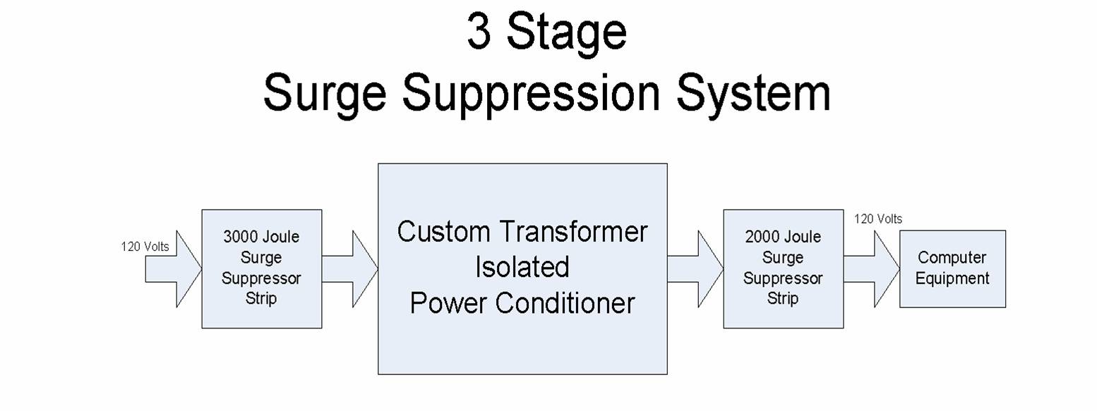
The 3 stage system consists of:

  1. a 3000 Joule commercial surge suppressor strip, with integral circuit breaker.
  2. a custom designed and built, transformers isolated power conditioner.
  3. a 2000 Joule commercial surge suppressor strip.


The 3000 and 2000 Joule commercial surge suppressor strips were the highest quality (i.e. expensive) that I could find.   But surge protection is so important, that I considered these insufficient.


Therefore, I additionally designed and built a custom transformer isolated power conditioner.   It contains a 2 KVA dry transformer and six metal oxide varistors.  It also contains four RC snubber networks for high frequency EMI attenuation.  The main purpose of the transformer is to provide additional series impedance.  The design of the power conditioner is covered in a separate blog.


The theory behind the entire scheme is that each stage of the surge suppression system helps dissipate the spike’s energy.   An applied voltage spike first is partially dissipated by the building’s line impedance and the first 3000 Joule suppressor strip.   The portion of the spike that gets through is next attenuated by the custom transformer isolated power conditioner.  In addition, this helps slow down steep wavefronts and reduce EMI.    The final 2000 Joule surge suppressor strip attenuates whatever spike remains.

A block diagram of the system is shown in the Visio diagram below.

3 Stage Surge Suppression System

3 Stage Surge Suppression System


Four Inches (4”) of Water in Transformer

August 11th, 2010 Comments off

MIDWEST is frequently asked about some of our unusual experiences over the years.  Things that happened that had no text book solution. Here is one of those experiences, having to do with an old outdoor askarel (PCB) filled transformer. The transformer was a transplant from indoor to outdoor. A little crazy, even in those days. This happened decades ago. Back when old askarel transformers were still sampled.  The fluid dielectric strength test results were horrible, 14 Kv. During their next plant shutdown, we inspected the transformer and found about 4” of water layered and floating on top of the askarel fluid. Askarel fluid weighed about 12.7 lbs. per gallon, so the lighter water, about 8 lbs per gallon, just mostly floated on the top of the dielectric fluid, askarel. The exposed glass rupture disk on top of the old power transformer had cracked when rained turned to ice during the winter. The internal high voltage (13,800 volts) leads, from the high voltage bushings to the transformer windings, actually passed through the layer of water. These leads were insulated, but not insulated against water. The secondary bushing leads were below the free water level.  The plant would be in crisis without this transformer. They had no spare replacement transformer. It would take too long to get a reconditioned, rebuilt or new transformer. So the plant engineer said, “It was working when we turned it off, so, when you’re done, we’re turning it back on.”  We removed the layer of free water; Added R-Temp Transformer Fluid to the proper level; Turned the transformer back on; and no noise, good. All the PCB contaminated fluid and debris was properly disposed at an EPA authorized facility. 


MIDWEST told the customer the transformer needed to be replaced as soon as possible.  There was an incipient, even imminent, failure.  The next time we heard from the customer was seven months later when the 1000 kva transformer failed.  Our advice was ignored. But we were amazed the transformer lasted that long.

Infrared Scanning of Electrical Systems

June 21st, 2010 Comments off

MIDWEST performed an Infrared Scan of the electrical system for a new customer.  They had two old outdoor oil filled transformers with load tap changers that had not been used in some time.  So when we scanned these old transformers, we made certain we scanned the load tap changer compartments.  Each tap changer was dangerously over heating. The electrician with us wondered why, since they hadn’t operated the tap changers in 20 years.  But tap changer contacts can cause coking, especially if they are not operated.  Later, during a scheduled maintenance outage, MIDWEST found both load tap changer compartments completely coked, full of black sludge.  The sludge had to be removed by hand, like scooping out sticky black mud.  Since they would never use the transformer tap changers again, MIDWEST removed the entire interior operating mechanisms and bussed the terminals. The old transformers were very lucky the tap changers didn’t fault. If they had, it would not have been cost effective to repair them.  It was just a matter of time before a catastrophic fault in a tap changer would have cost them a transformer.  We have seen this problem before in old transformers.  In this case, certain failure was avoided, and they reused the transformer after the repair. Infrared Scanning is very important, even on old, obsolete transformers and switchgear. 

Pad Mount Transformer

June 14th, 2010 Comments off

Transformers come in many different flavors of course. One popular type found in and out of industry is the pad mount transformer. Most people have seen these without knowing what they were seeing. If you look outside an apartment complex, grocery store, or small industrial facility you might see a green colored rectangular shaped enclosure sitting on a concrete pad at ground level. That more than likely would be a pad mount transformer. What makes these unique in the family of transformers is their placement outside of a secure restricted access area such as that of a typical electrical substation. These units are designed to be placed in public access areas eliminating the need for a fenced secure area. These units are fully enclosed and have locking cabinet doors preventing public access to high voltage cable connections.


Although these transformers are fully enclosed and locked, it would be misleading to say they were safe since they are still energized. Concrete posts or steel guard rails are often placed around pad mount transforms to protect them from vehicle traffic. Pad mount transformers are reliable and aesthetically pleasing units with typically underground cable feeds. Although they can be fed from the side or from overhead. These transformers are for outdoor use and as such are usually mineral oil filled.


If you have questions about old pad mount transformers, call MIDWEST. They sell, rent, repair and buy them. They would be more than happy to speak to you.

Transformers In Parallel

June 10th, 2009 Comments off

Transformers are placed in parallel by electric utilities when they want to provide a ‘stronger’ voltage source and will result in higher available fault current that can be delivered downstream.  Usually the utility transformer can serve its own load but two are put together to achieve with a ties primary and secondary bus to ‘stiffen’ the voltage to ride through system load changes.

Yes the utilities have to worry about automatic load tap changers that could hunt forever.

Some industrial customers try this method to serve a load that is too large for a single transformer.  This arrangement has to be done carefully or you can damage one or both of the transformers.  You need an exactly matched pair of transformers or transformers of different manufacturers with identical characteristics or circulating currents can build up in the parallel connection that consumes energy and does not pass to the load.  Routine maintenance of the parallel connected transformers in the non-utility world is nixed because neither transformer is big enough to serve the load on its own.  This would mean extended outages to the load during maintenance of either transformer.  Parallel connections of transformers in the industrial world are usually not attempted because the lack of maintenance makes for a less reliable installation.  Transformers come in various sizes and the best or optimum transformer size is one that can adequately handle its load all by itself.

POWER TRANSFORMERS – PART 1:

April 29th, 2009 2 comments

By Larry Dahlgren


So someone told you should obtain a transformer.


Before you open your wallet and buy the first transformer you meet, let’s consider the situation a bit.

Dry Type Transformer

Buy Dry Type Transformers

You might have just moved your equipment to a new facility and the new location seems to be electrically different from your former location.  You do not see the familiar types of disconnects and plugs your former location had or your machines used to be hard wired and now, at their new home, you have a collection of machines with pigtail wires and you are unsure where to connect them.  Maybe you just picked up a spare to one of your existing machines or added a machine because there are many available at auction.


You get them to your shop and now find the nameplate voltage is different than your building voltage.


A.        AVAILABLE VOLTAGE

Is the actual voltage at the new location any different from the old location?

It could be the same and it might just be referred to by some other name.

Maybe that machine you just picked up at the fire sale has a voltage tolerance that will mean it can work just fine on your available supply.


Consider this single phase example:

There are those who refer to the voltage that comes from a typical wall outlet as 120 Volts.  A generation ago that same voltage used to be called 115 Volts or 110 Volts.


Today the do-it yourselfer may connect an electric water heater or electric dryer or range to 240 Volts from a breaker fed from both sides of the common household circuit breaker cabinet.  Thirty years ago the water heaters were connected across 230 Volts from both sides of the fuse box if the thinking is that the wall outlets were good for 115 Volts.  Maybe that water heater used to be wired to 220 Volts coming from both sides of the fuse box that powered all of the 110 Volt outlets. 


This can become complicated even more in multi family buildings, served by the utility with 208Y/120 volts, where each unit is served from two hot legs and the neutral.  In that case the wall outlets are still at 120 Volts but there is only 208 Volts between the two hot legs so the dryer and water heater are fed from 208 Volts.  Trouble is, a lot of folks just say the specialty socket for the stove or range has 220 Volts and then you have to investigate further and measure safely so you know the actual voltage that is present.


The same type of confusion can extend into the three-phase industrial setting. 


People refer to one type of nominal, three phase, three wire voltage as 440, 460 or 480 Volts.  Some refer to another type of nominal, three phase, three wire voltage as 220, 230 or 240 Volts.


The two, common, three phase, four wire, nominal voltages are 480Y/277 Volts and 208Y/120 volts.


Measuring (safely) you may discover that the actual voltage, over time, could vary above and below these nominal values.  The voltage at times could reach as high as 504 Volts or drop to only 456 volts.  Other times the 240 Volt nominal voltage could swing as high as 252 Volts or as low as 228 Volts.  Watch out because occasionally 208 volts can swing as high as 218 Volts.  You are then left to wonder if a measurement of 216 Volts could mean a stiff 208 Volt system or a very soggy 240 Volt system.  Determining the actual voltage and the nominal voltage are critical in the selection of a transformer. 


The same holds true for your wall outlets where the acceptable voltage, according to your local power company, can swing from 95% of 120 volts (114 volts) to 105% of 120 Volts (126 volts).  Should the voltage drops to 90% of 120 Volts (108 Volts), call your power company.  


Hey 114 Volts is only a volt shy of 115 Volts.  This means your parents were right again; this time about wall outlets.


Next time we will discuss the equipment you energize with the voltage you have.


See Part 2


Good Luck, be safe and happy transforming.