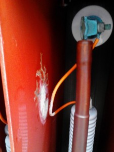
High Voltage Switch Interphase Barrier being destroyed by high voltage corona and tracking
If you’re a manufacturing plant and your main electrical power transformer is a 10 MVA, 10,000 kva, oil filled station type transformer, you’re probably not interested in failure modes and probability analysis from your service company. You just want to know everything is being done to make sure it doesn’t failure. In the world of sophisticated test procedures and test equipment and lengthy specifications for the application of the procedures to your 5 MVA, 10 MVA, or even 50 MVA high voltage power transformer, there is still need for old fashion maintenance and inspection services. Too often the main high voltage power transformer for a facility can never be turned off because of the interruption of production or data processing. We know that is the real world today and we have to deal with it in the best way possible to maintain reliability. Periodic combustible gas analyses and routine oil analysis are extremely useful. But there is still room for some old fashion basic maintenance services. MIDWEST likes “Ultrasonic Scanning” of medium voltage and high voltage equipment for indications of destructive corona or tracking. We recommend this on high voltage equipment, especially metal enclosed. And if you have a 20 MVA oil filled power transformer, you have something in front of it to protect it. If that protection fails, your transformer becomes very unhappy. For example, it is not unusual for us to find destructive corona or tracking damage to the inter-phase barriers in the high voltage switch protecting a power transformer. A good example is a lightning arrester lead that rests against the inter-phase barrier and is slowing destroying the barrier. Eventually one of the barriers will fail, usually a phase to phase fault and frequently during a lightning storm when a voltage surge screams down the line into the high voltage switch. Ultrasonic Scanning of the high voltage transformer main switch would catch this before it fails. Not real sophisticated, but an extremely effective preventive procedure. Find it, Fix it before it fails.
Categories: Uncategorized Tags: Combustible Gas Analyses, Destructive Corona, Destructive Tracking, electrical power transformer, High Voltage Equipment, High Voltage Switch, inter-phase barriers, Lightning Arrester, MVA, oil filled transformer, power transformer, Routine Oil Analysis, Ultrasonic Scanning
The best test to predict the reliable operating condition of an oil filled transformer is the combustible gas-in-oil analysis. Using a syringe, 40 cc of oil is taken from the transformer and analyzed. When threshold levels of specific gases in the oil are reached, protocol demands appropriate action be taken. This is an extreme oversimplification of a combustible gas-in-oil analysis.
One such case involved a 3000 kva, 25 kv primary, 600 volt secondary, foundry furnace transformer. The oil test results indicated the transformer began generating high levels of acetylene. Additional tests were performed and the transformer was shut down and taken out of service. A temporary transformer was put in its place to continue plant production. The defective transformer was sent out to be rebuilt.
Furnace transformers are special breeds of cats, designed to withstand the stresses of heavy shifting loads. Often times these transformers are pushed to the max in terms of load limits. Based on secondary ampere readings, this transformer was pushed to over 100% of rated load capacity, creating high thresholds of heat in the windings. Transformers don’t much like that too well. Heat puts all kinds of funny stresses on the internals of transformers.
In two months time the rebuilt transformer was put back in service and life continued on.
One common concern with pad mount transformers is in the area of oil sampling. Companies with large pad mount transformers may sample and test the oil in the transformers annually to determine the reliability of the transformer. The condition of the oil reflects the current state of the transformer. Now here’s where it gets tricky. Large pad mount transformers are designed with two cabinet doors. One door exposes the high voltage cables and bushings and the other door exposes the secondary, low voltage, side. The sample valve can be located in either compartment but most of the time the valve is located in the secondary cable side. Years ago it was not uncommon for an intrepid technician with nerves of steel to pull an oil sample from an energized pad mount transformer, the valve being located at the bottom of the transformer while hot cable lugs were located only a couple feet above the oil valve. With safety becoming a paramount concern in industry today, it is no longer prudent nor standard practice to pull an oil sample on an energized pad mount transformer. The hot lugs being within short reach of the technician create a shock hazard. And the secondary side of a transformer is one of the most dangerous arc flash hazards there is. Oil sampling is now performed only during scheduled shutdown of the transformer.
However, there still remains somewhat of a challenge when it comes to pulling an oil sample from a pad mount transformer. The secondary compartment of pad mount transformers can be a pretty fully house. There may be as many as six cables attached to each secondary bushing, making it very difficult to access the sampling valve through that jungle of vines. One way around this, literally, and we’re finding it used more and more in industry, is extending the sample value system to a small secure box on the exterior of the transformer enclosure. The valve would then be enclosed in a newly created box with a locked access door mounted on the exterior wall of the cabinet. In this way the transformer can be sampled at any time, while energized, without exposing the technician to shock or arc blast hazards.
