Old Obsolete Good Scrap Transformers

November 8th, 2010 2 comments

MIDWEST was asked what we did with perfectly good obsolete or old used transformers. Bit of an oxymoron since obsolete might be understood to mean no longer any good. But the intent of the question was obvious. Transformers that are too old to be sold in the used transformer market might be maintained in MIDWEST’s pool of rental, temporary, and emergency transformers or they are just scrapped. Typically a rental transformer is just for temporary use. But we have had many transformers on rental for over a year. Especially larger Mva transformers. We have a few we didn’t scrap out but kept around solely because of the special voltages or size or physical configuration, to be used in those rare occasions when a manufacturing company, for example, is in trouble with delivery of a special replacement transformer. This usually happens when they had a non typical transformer suddenly fail. The difference between these special temporary transformers, which we sometimes call cling-ons, and our rental transformers is that we’d really like to get rid of the cling-ons. But about every time we think we’ll scrap out an obsolete old unit, we get a desperate call and it is the only thing that will work and the only one the customer can find. So it is resuscitated again and lives on. We do have fewer of these than ten years ago. We just scrapped out a 2000 Kva oil filled power transformer, 13,200 volts to a variable secondary of 120 volts to 600 volts. Weighed 18,000 pounds. A big old power transformer, specially built for a transformer power lab about 60 years ago. We finally got rid of it because we never rented it in two decades; And we did not have a good biography on the unit, although all our test results were good. The install cost as a rental, emergency, or temporary transformer would have been potentially huge because of the oversize and weight due to the many voltage taps. A potential customer would only need one functional voltage and would be paying a premium for a monster oil filled power transformer when they probably could find a unit with their specific voltage. Plus MIDWEST can not rent a transformer we no longer have full confidence in, even during an emergency. In the last month we designated over ten transformers to the scrap heap. Mainly because of a lack of full confidence in their reliability, even though many of them had good test results. MIDWEST knows electrical tests, on used oil filled and dry type power transformers, are not a perfect indication of the condition of the transformers. So MIDWEST looks for reasons to get rid of the old and the cling-ons.
20 Mva Power Transformer Leaking Bushing

October 28th, 2010 Comments off

Sometimes simple oil filled power transformer repairs can be made very complicated by seemingly small hidden details. Sometimes the circumstances that create the complication evolved over time. Or, in some cases, it was just poor engineering. In this case the new transformer, switchgear, and substation structure were pieced out to different engineers and contractors, 20 years past. Not a good idea. Here’s an example of a job made hard by the lack of foresight and design coordination   An electric utility had a 20 Mva power transformer with side mount secondary bushings, 15 Kv. The bushings connected to a 15 Kv enclosed busway that ran from the transformer to the 15 kv switchgear inside the building. The bushings were side mounted in a throat for connection to the busway.  One of the bushings had a small leak from the crown gasket. But the oil was pooling and dripping slowly from the throat enclosure. This would normally not be a very complicated repair, even though the leaking bushing would have to be removed to replace the gasket. Access to the bushing connections inside the transformer were very easy. Access for proper oil handling equipment for work on a 115 kv high voltage transformer was easy.  But the bushings were not top mounted. They were side mounted and the bushings had to be removed 24 inches in order to get them out of the transformer side throat.  Usually you just remove the immediate flexible connections to the bushings and one section of busway and have at it. In this case, because of the configuration and supports for the busway, three sections of busway, including a 90, would have to be disassembled. And this was huge bus for a 20 Mva transformer. It was as if the busway was erected first and then the transformer slid in place to connect to the bus. Then overhead structure installed and more infrastructure install adjacent to the transformer such that you couldn’t move or pick the transformer, even if you wanted to, in order to save time.  No thought was given to access or service of the secondary bushings.  So the Utility cleaned up the oil and redefined the leak as a weep, to be monitored.  They couldn’t handle a 48 hour outage to do the repair. Whether this was a 10 Mva, 20 Mva, or 30 Mva oil filled power transformer, the simple leak repair would be a monstrous job.  But sooner or later the old power transformer will have to be repaired.

Electrical Transformer Hot Seat

October 6th, 2010 Comments off

When Infrared Scanning electrical power distribution systems, including general purpose dry type transformers, MIDWEST frequently finds interesting, strange, and even dangerous situations that have nothing to do with Infrared Thermography.  Visualize a make shift rest area in a manufacturing plant. This area was next to the tool room.  There were two panel boards, some wire way with switches above it, and two small general purpose dry type transformers next to the panel boards. One transformer looked like an old 75 kva 480 volt to 208 volt transformer and the other looked like a new, maybe 25 kva general purpose transformer.  Both of the dry type transformers were very warm. On top of the large dry type transformer was a small microwave and a coffee maker.  On top of the small dry type transformer was a cushion.  This looked like a pretty comfortable kitchenette set up.


Anyone electrical should recognize the danger of coffee, liquid, around an open air, air cooled, general purpose dry type transformer. A liquid spill would seem inevitable.  Just a matter of time. Even if the transformer had weather shields, no one should ever be around it with liquid.


The smaller electrical power transformer was just a nice warm seat.  We have seen this a million times, especially in warehouse and other unheated or poorly heated manufacturing and industrial areas.  Usually the folks using these transformers as seat warmers are not electrical and have no idea of the danger below. 


A 75 kva 480 volt air cooled transformer can let out a horrific blast if the primary conductors short out. The transformer would become an instant hot seat and the arc blast from the open top vents could cause horrible burns to anyone nearby.  Add to this the shock hazard. An arcing fault could go to ground and some one touching the transformer could receive a deadly shock. Or something could easily be stuck into the vents and contact live conductors. We see these general purpose air cooled dry type transformers everywhere, and in sizes ranging from 5 kva to 500 kva.  When we see this danger, we politely let the person know the risk of shock or burn.  In a second, that nice warm seat could turn into a deadly hot seat. And that coffee pot stand could be the source of a deadly shock or horrible arcing burn, in a second.

Isolation Transformers, Metal Oxide Varistors, and their Role in Surge Suppression

September 22nd, 2010 2 comments

A recent series of blogs by MIDWEST’s Engineering Department at Circuit Breakers Blog and Power Transformers Blog have described the failure of some surge suppressor strips, and the author’s custom transformer isolated power conditioner and three stage surge suppression system.

The common thread in these blogs is surge suppression of voltage spikes utilizing metal oxide varistors.    

Voltage spikes, or transients, can be produced by a wide variety of electrical devices, such as electric motor starters, circuit breakers opening or closing, electrical switchgear, motor control centers, soft starters, vacuum circuit breakers, industrial transformers switched on or off, motor contactors, and of course lightening strikes.

There is a little known effect that metal oxide varistor surge suppressors employ in order to attenuate voltage spikes.  This was first researched by a highly respected PhD. on our staff in the process of writing a White Paper on varistor protection of industrial power electronics.  The effect is the series impedance provided by the power company’s distribution system, the building wiring, the surge suppressor strip’s line cord, substation transformers, pole transformers, and isolation transformers.  This aspect is never really mentioned in the literature.    

The line impedance consists of a small resistance, and a small but important inductance.   Fourier analysis tells us that a spike is mostly high frequency.  Thus, the inductive reactance at spike frequencies can be considerable. This reactance, and to a lesser extent, the resistance, is the vital ingredient that makes a metal oxide varistor suppression scheme work in the first place.  Inductive reactance equals 2 times pi times frequency in hertz times inductance in Henries XL=2*π*f*L.


Normally, everybody thinks that when a large spike hits a varistor, the varistor conducts huge currents and “eats” the spike.  But, what is never mentioned, is that the huge current also passes through the equivalent series impedance of the line.  Kirchhoff’s voltage law says the huge voltage has to be impressed somewhere.  If we assume that a 10 KV spike is applied, the varistor might conduct a very large current, hundreds to a few thousand amperes.  According to the voltage-current characteristic VI curves of a Max Allowable Voltage of 130 VAC RMS varistor, the varistor might have about 300 Volts across it.  What happens to the other 9.7 KV?  As the huge current passes through the line reactance, the majority of the spike voltage is impressed across the line reactance.  The huge spike voltage is not impressed across the varistor.  But, if the 10 KV voltage would instead be impressed across the varistor, such as might happen from a very nearby lightening strike, the varistor would conduct tens of thousands of amps, and instantly vaporize, along with a lot of the wiring in the house.  But if instead the lightening strike is 1 mile away, there is 1 mile of resistance and reactance to act as a  current limit by having most of the 10 KV dropped across it.


Thus, what really happens during a high voltage spike is that the varistor starts conducting appreciably around 300 Volts, and conducts hundreds or thousands of Amperes.  The applied voltage spike is then impressed across the line reactance, according to Ohm’s law.  Thus it is actually the line reactance that “eats” the spike voltage.  The varistor is only the current path for the spike current.  Of course, a large power dissipation also occurs in the varistor too.  It is usually only this dissipation that is ever mentioned or considered.  But the line impedance is truly the vital element, as it limits the varistor current and dissipations to reasonable values. 

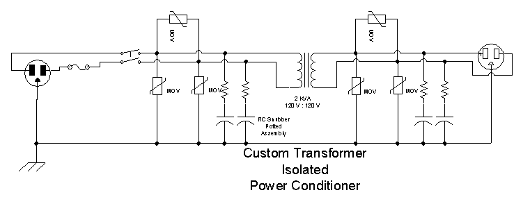
Now, with this said, the real value of the isolation transformer in the line conditioner can be seen.  Its leakage reactance provides a large series impedance for any spikes that get through to the secondary.  The secondary’s spike elimination network starts to conduct large currents, and the spike’s voltage is impressed across the transformer’s leakage reactance.


Isolation Transformers Isolated Power Conditioner Block Diagram 1

Isolation Transformers Isolated Power Conditioner Block Diagram 1


Isolation Transformers Isolated Power Conditioner Schematic

Isolation Transformers Isolated Power Conditioner Schematic

Transformer Valve Risky Replacement

September 17th, 2010 Comments off

Over the years MIDWEST has had to do some creative and sometimes risky work. These things typically occurred when there were very unusual or strange circumstances.  And they were usually performed against our advice to customers that had no easy or inexpensive alternative. When we say risky, we are not talking about risk to life safety. This following example was a very simple task, unless something went wrong. We just needed to replace the lower main valve of a 2000 kva oil filled power transformer without draining the transformer first.  The owner could de-energized the transformer for a short time, but could not tolerate an outage long enough to drain the oil, change the lower main valve, and replace the oil.  They were willing to take on the risk of changing the value with the transformer full, and de-energized and grounded, of course. Actually, we have changed valves on smaller and larger power transformers, but the circumstances were always different.  We knew in this case we would end up with possibly two gallons of messy waste oil, even if things went well. Our procedure was as follows. Loosen the existing lower valve from the 2000 kva power transformer lower valve stem. Prepare the replacement valve such that it could be immediately installed after the existing valve was removed. Secure the area. A large spill pan was placed under the existing transformer valve and stem. All the needed tools and the new replacement valve were placed inside a sturdy large clear plastic bag, including a pipe cap, just in case. A vacuum was pulled on the transformer. The plastic bag was secured about the pipe stem at the bottom of the old transformer. The bag was big enough to hold and manipulate the valves.  Then, like two lab rats, one technician removed the old valve while a second technician held the new valve adjacent the existing valve. The old valve was removed and slide to the side just as the new valve was slide into place and screwing onto the pipe stem. Works well if you catch the threads on the first try.  Either way, one ends up with a blast of old oil all over the inside of the bag.  If the valve quick exchange fails, the cap is put on the stem. It is amazing what happens inside the clear plastic bag in the seconds it takes, hopefully, to change the valve.  This task may sound like a good idea, but we do not recommend it. And we have a hundred years of experience working on old and new power transformers. We’re good at it and we like it. But we know old oil filled electrical power transformers are good at hiding defects until you try to work on them.  Sometimes the messy work is the fun work on transformers.  

Transformer Isolated Surge Suppression System

September 8th, 2010 1 comment

Recent circuit breaker blogs by MIDWEST have dealt with circuit breakers and surge suppressors.   For expensive computer equipment, superb surge suppression is vital.    Surge suppression is exceedingly cheap insurance for such applications.  The initial / replacement equipment costs can be expensive.  But even more importantly, downtime and data loss can be catastrophic.


In fact, when putting together my own home computer system, I considered surge suppression so extremely important, that I put together my own 3 stage surge suppression system.


The 3 stage system consists of:

  1. a 3000 Joule commercial surge suppressor strip, with integral circuit breaker.
  2. a custom designed and built, transformers isolated power conditioner.
  3. a 2000 Joule commercial surge suppressor strip.


The 3000 and 2000 Joule commercial surge suppressor strips were the highest quality (i.e. expensive) that I could find.   But surge protection is so important, that I considered these insufficient.


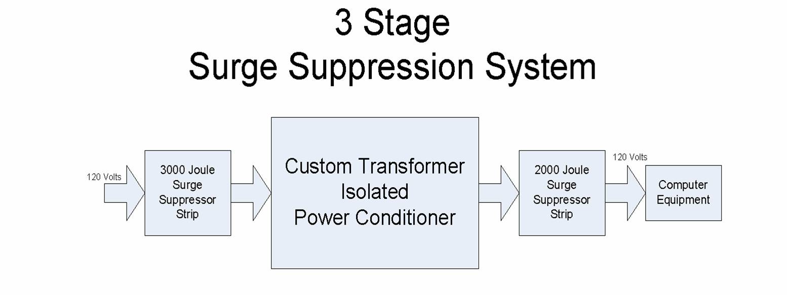
Therefore, I additionally designed and built a custom transformer isolated power conditioner.   It contains a 2 KVA dry transformer and six metal oxide varistors.  It also contains four RC snubber networks for high frequency EMI attenuation.  The main purpose of the transformer is to provide additional series impedance.  The design of the power conditioner is covered in a separate blog.


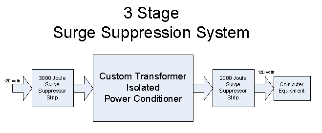
The theory behind the entire scheme is that each stage of the surge suppression system helps dissipate the spike’s energy.   An applied voltage spike first is partially dissipated by the building’s line impedance and the first 3000 Joule suppressor strip.   The portion of the spike that gets through is next attenuated by the custom transformer isolated power conditioner.  In addition, this helps slow down steep wavefronts and reduce EMI.    The final 2000 Joule surge suppressor strip attenuates whatever spike remains.

A block diagram of the system is shown in the Visio diagram below.

3 Stage Surge Suppression System

3 Stage Surge Suppression System


Four Inches (4”) of Water in Transformer

August 11th, 2010 Comments off

MIDWEST is frequently asked about some of our unusual experiences over the years.  Things that happened that had no text book solution. Here is one of those experiences, having to do with an old outdoor askarel (PCB) filled transformer. The transformer was a transplant from indoor to outdoor. A little crazy, even in those days. This happened decades ago. Back when old askarel transformers were still sampled.  The fluid dielectric strength test results were horrible, 14 Kv. During their next plant shutdown, we inspected the transformer and found about 4” of water layered and floating on top of the askarel fluid. Askarel fluid weighed about 12.7 lbs. per gallon, so the lighter water, about 8 lbs per gallon, just mostly floated on the top of the dielectric fluid, askarel. The exposed glass rupture disk on top of the old power transformer had cracked when rained turned to ice during the winter. The internal high voltage (13,800 volts) leads, from the high voltage bushings to the transformer windings, actually passed through the layer of water. These leads were insulated, but not insulated against water. The secondary bushing leads were below the free water level.  The plant would be in crisis without this transformer. They had no spare replacement transformer. It would take too long to get a reconditioned, rebuilt or new transformer. So the plant engineer said, “It was working when we turned it off, so, when you’re done, we’re turning it back on.”  We removed the layer of free water; Added R-Temp Transformer Fluid to the proper level; Turned the transformer back on; and no noise, good. All the PCB contaminated fluid and debris was properly disposed at an EPA authorized facility. 


MIDWEST told the customer the transformer needed to be replaced as soon as possible.  There was an incipient, even imminent, failure.  The next time we heard from the customer was seven months later when the 1000 kva transformer failed.  Our advice was ignored. But we were amazed the transformer lasted that long.

Transformer Load Imbalance

July 15th, 2010 1 comment

A MIDWEST Thermographer found an interesting problem with a 208 volt, 3 phase, 75 kva dry type general purpose transformer.  The Infrared Scan showed the enclosure of a Square D transformer was much warmer on one side compared to the middle and other side. It was an older transformer and had been in service for many years. An enclosure must re-emit enough heat from the air cooled transformer and the difference in heat from one area of the transformer to another must be substantial enough for the Thermographer to see the difference in heat pattern.  But when you’ve scanned 1000s of these dry type transformers over 15 years, you have a pretty good idea of what’s normal or not.  A load check revealed one phase was at 220 amps, another at about 115 amps, and the third phase 90 amps.  They definitely had a large load imbalance on their old transformer. The maintenance man said they had been having nuisance tripping on the output breaker, but when he checked the load, there was less than 100 amps, 50% load. Unfortunately he only checked the load on one phase and got unlucky enough to pick the lightest loaded phase.  But it was also very easy for our Thermographer to see the load imbalance on the circuit breakers on the load and line side of the transformer.  It is amazing how tough these old air cooled transformers are.  10 kva to 500 kva, general purpose dry type transformers are found everywhere.  Some are real dinosaurs, beyond old, but not obsolete because they are still running.  Some over 70 years. A couple other things about these really old dry type transformers. They were so overbuilt that they can be very forgiving of overloading and they can be really loud.  

Deadly Transformer Vault

July 7th, 2010 Comments off

Here is another MIDWEST transformer horror story.  This involves a 1000 kva indoor dry type power transformer, 13.2 Kv to 120/208 volts.  The first time we saw this transformer, we thought it was just a spare new transformer core and coil being stored in one of the customer’s equipment rooms. It looked just like a replacement transformer because the core and coil were not in a metal enclosure.  It was out in the wide open area of the room with no protective enclosure or barriers, nothing to protect it. To our great surprise, we soon realized that this old transformer was energized.  The hmmm and the exposed wires connected to it were a big tip. One had to walk around the transformer to get to one corner of the room.  Beside electrical conduits, there were other overhead pipes in the room, plus communication cables.  There were electrical panels and non electrical equipment in the room.  The electrician said he was told it was okay because it was a locked door and nobody was suppose to go in there.  He told his boss that he thought it was very dangerous, but he was told it met code. He thought the whole thing was nuts. We asked where the key was secured so that unqualified personnel could not enter the room, which they called a vault. The key was hung on a nail over a nearby doorway going into a mechanical equipment room. This was considered secure because nobody knew what the key was for, except the ‘right’ people.  We explained the extreme shock hazard and arc flash hazard to anyone, even qualified personnel, entering the room and the fact that unqualified personnel may acquire access to the room because of the key location.  In plain English, this set up was crazy.  To this day, nothing may have changed, because someone decreed “it met code.”   

Replacing old Allis Chalmers Transformer with new oil filled transformer

June 30th, 2010 Comments off

MIDWEST frequently replaces old oil filled transformers with more efficient new oil filled power transformers. Being a specialty engineering firm, we usually get involved when the project is messy. We had a recent project involving replacement of very old Allis Chalmers 600 kva and 1000 kva oil filled conservator tank transformers.  These were monster units compared to the size the replacement transformers, which were 1000 kva.  As a training exercise, MIDWEST had a shop crew tear one of the old transformers apart. They quickly found out that the bushings for the old transformers extended twice as far inside the tank as they did outside. These may have been obsolete transformers, but they were built like battleships and who knows how long they may have lasted. The crew got a good look at the workings of the conservator tank.  Then they removed the top. The old transformer had a bolted on top and the core and coil assembly was bolted to the top, such that the transformer core and coil came out of the tank when the top was lifted. The crew was surprised at how small the core and coil assembly was. They thought it probably took up only the bottom third of the tank. We know that new replacement transformers are much smaller and lighter than the old and obsolete transformers used for manufacturing plants across the country. When we do a power transformer replacement, we seldom have to worry about space when the transformer being replaced is 60 years old.  Actually we have to provide a raised concrete pedestal when installing a new oil filled power transformer in place of one of these old units. So, as strange as it may be in this case, for a replacement electrical power transformer, new is small and old is tall. And seeing is believing.