Isolation Transformers, Metal Oxide Varistors, and their Role in Surge Suppression
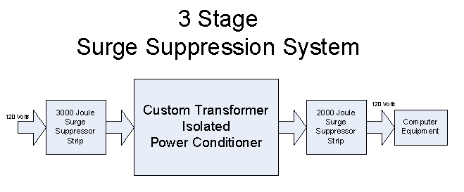
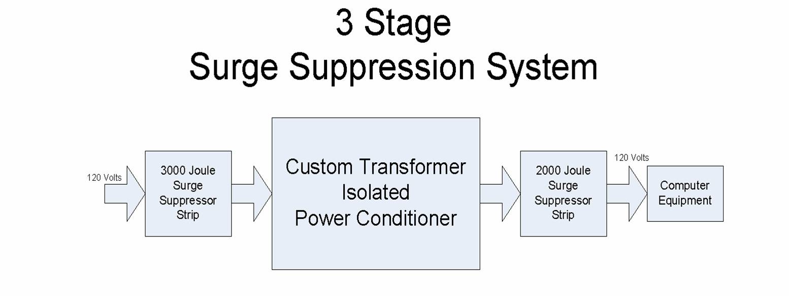
A recent series of blogs by MIDWEST’s Engineering Department at Circuit Breakers Blog and Power Transformers Blog have described the failure of some surge suppressor strips, and the author’s custom transformer isolated power conditioner and three stage surge suppression system.
The common thread in these blogs is surge suppression of voltage spikes utilizing metal oxide varistors.
Voltage spikes, or transients, can be produced by a wide variety of electrical devices, such as electric motor starters, circuit breakers opening or closing, electrical switchgear, motor control centers, soft starters, vacuum circuit breakers, industrial transformers switched on or off, motor contactors, and of course lightening strikes.
There is a little known effect that metal oxide varistor surge suppressors employ in order to attenuate voltage spikes. This was first researched by a highly respected PhD. on our staff in the process of writing a White Paper on varistor protection of industrial power electronics. The effect is the series impedance provided by the power company’s distribution system, the building wiring, the surge suppressor strip’s line cord, substation transformers, pole transformers, and isolation transformers. This aspect is never really mentioned in the literature.
The line impedance consists of a small resistance, and a small but important inductance. Fourier analysis tells us that a spike is mostly high frequency. Thus, the inductive reactance at spike frequencies can be considerable. This reactance, and to a lesser extent, the resistance, is the vital ingredient that makes a metal oxide varistor suppression scheme work in the first place. Inductive reactance equals 2 times pi times frequency in hertz times inductance in Henries XL=2*π*f*L.
Normally, everybody thinks that when a large spike hits a varistor, the varistor conducts huge currents and “eats” the spike. But, what is never mentioned, is that the huge current also passes through the equivalent series impedance of the line. Kirchhoff’s voltage law says the huge voltage has to be impressed somewhere. If we assume that a 10 KV spike is applied, the varistor might conduct a very large current, hundreds to a few thousand amperes. According to the voltage-current characteristic VI curves of a Max Allowable Voltage of 130 VAC RMS varistor, the varistor might have about 300 Volts across it. What happens to the other 9.7 KV? As the huge current passes through the line reactance, the majority of the spike voltage is impressed across the line reactance. The huge spike voltage is not impressed across the varistor. But, if the 10 KV voltage would instead be impressed across the varistor, such as might happen from a very nearby lightening strike, the varistor would conduct tens of thousands of amps, and instantly vaporize, along with a lot of the wiring in the house. But if instead the lightening strike is 1 mile away, there is 1 mile of resistance and reactance to act as a current limit by having most of the 10 KV dropped across it.
Thus, what really happens during a high voltage spike is that the varistor starts conducting appreciably around 300 Volts, and conducts hundreds or thousands of Amperes. The applied voltage spike is then impressed across the line reactance, according to Ohm’s law. Thus it is actually the line reactance that “eats” the spike voltage. The varistor is only the current path for the spike current. Of course, a large power dissipation also occurs in the varistor too. It is usually only this dissipation that is ever mentioned or considered. But the line impedance is truly the vital element, as it limits the varistor current and dissipations to reasonable values.
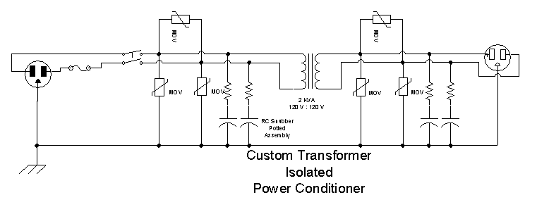
Now, with this said, the real value of the isolation transformer in the line conditioner can be seen. Its leakage reactance provides a large series impedance for any spikes that get through to the secondary. The secondary’s spike elimination network starts to conduct large currents, and the spike’s voltage is impressed across the transformer’s leakage reactance.

Isolation Transformers Isolated Power Conditioner Block Diagram 1

Isolation Transformers Isolated Power Conditioner Schematic
